eng
 English
 русский
 Español
 Français
Home / News / Industry News / Cold Junction of a Thermocouple: Why It Really Matters and How CJC Works

Industry News
Oct 16,2026
Cold Junction of a Thermocouple: Why It Really Matters and How CJC Works
If you have ever compared two thermocouples on the same pipe and watched them disagree by a few degrees, the sensor tip probably was not the problem. More often, the answer sits at the other end of the loop, in the terminal block where the thermocouple wires meet the instrument. That connection point is the cold junction, and once you understand what it does, thermocouple measurement stops feeling like guesswork.
This article walks through what the cold junction is, why a thermocouple cannot report an absolute temperature without it, how cold junction compensation works in modern instruments, and which habits keep the reference junction from quietly spoiling your data.
How a Thermocouple Produces a Voltage
A thermocouple is two wires of dissimilar metals joined at one end. That joint, the measuring or hot junction, is what you place in the process. When the two metals see a temperature difference between the joined end and the free ends, the Seebeck effect generates a small voltage, typically tens of microvolts per degree Celsius.
The detail that catches people out is this: that voltage does not correspond to the measuring junction temperature alone. It corresponds to the difference between the measuring junction and the point where the wires terminate. A type K thermocouple produces roughly 41 microvolts per degree Celsius, so a 5 °C shift at the terminals shows up as a 5 °C shift in the reading, even though the process never moved.
What Exactly Is the Cold Junction?
The cold junction, also called the reference junction, is formed where the thermocouple or its extension wires connect to the reading instrument: a transmitter terminal block, a controller input, a data logger, or a temperature transmitter.
Two things about it are commonly misunderstood:
- It is not simply room temperature. It is the actual temperature of those terminals at that moment, under whatever drafts, enclosure heat and cable loading exist.
- It is not always one convenient spot. Every intermediate connection made with the wrong wire creates an extra junction, and each one contributes its own voltage.
If copper screws or circuit board tracks touch the thermocouple wires, those contact points become part of the thermoelectric circuit. Keeping the terminal area isothermal, meaning all connections sitting at the same temperature, is the physical basis of good cold junction design.
From Ice Baths to Electronic Compensation
For much of the last century, the reference junction was held at a known 0 °C in a flask of melting ice. The measured voltage could then be compared directly with published tables built on that reference. It was accurate, and it is still the idea behind the standard thermocouple tables used today, but it is hardly practical on a petrochemical unit or beside a heat treatment furnace.
Modern instruments solve the problem electronically. Rather than forcing the cold junction to 0 °C, they measure its actual temperature and add the voltage the thermocouple would have produced if its reference were at 0 °C. That added quantity is the cold junction compensation voltage.
How Cold Junction Compensation Works
Inside a transmitter, controller or data acquisition card, the process breaks down into three steps.
- Measure the terminal temperature. A small RTD, thermistor or silicon sensor sits beside the terminal block, as close to the real junction as the layout allows.
- Convert that temperature into an equivalent thermocouple EMF. Using standard tables for the thermocouple type in use, the instrument works out the voltage that would appear if the measuring junction were at that terminal temperature while the reference stayed at 0 °C.
- Add and linearize. The compensation voltage is added to the measured signal, and the total is converted through polynomials or look-up tables into a final temperature value.
Because the correction depends on the thermocouple type, compensation is only valid when the instrument input, the sensor and the extension wiring all match. A type K sensor feeding a transmitter configured for type J gives a systematic offset that no amount of recalibration will remove. Software-based compensation in a data acquisition system follows the same logic, but the reference sensor often sits further from the terminals, and that distance is where accuracy is most easily lost.
Common Cold Junction Pitfalls
Most cold junction problems we hear about fall into a handful of patterns. The table below summarizes what typically goes wrong and what tends to fix it.
| Symptom | Usual cause | Practical remedy |
|---|---|---|
| Reading drifts when the cabinet door opens | Terminal block is not isothermal; reference sensor not thermally coupled to it | Shield terminals from drafts and mount the reference sensor against the block |
| Steady offset that recalibration cannot remove | Copper extension wire or a mismatched alloy creating unintended junctions | Replace with the correct thermocouple grade extension or compensation wire |
| Offset grows as the enclosure warms | Heat generating components mounted below the terminals | Move power devices away and add a thermal break between heat sources and terminals |
| Reading drops or spikes at high process temperature | Compensation wire used beyond its rated temperature, or reversed polarity | Check polarity and wire grade, and match the rating to the installation |
| Two channels disagree on identical sensors | Different terminal temperatures across a multi channel input card | Keep channels isothermal or use a transmitter with integral compensation at each sensor |
Extension and compensation wire deserves a special mention, because it is the part of the loop most often replaced with whatever was in the store room. Copper cable is fine for carrying a 4-20 mA signal, but it cannot carry a thermocouple signal without creating a new junction at each end. Compensation wire is made from alloys matched to the thermocouple type, and its temperature rating has to cover the hottest point it passes, including any section running across a hot vessel or furnace casing.
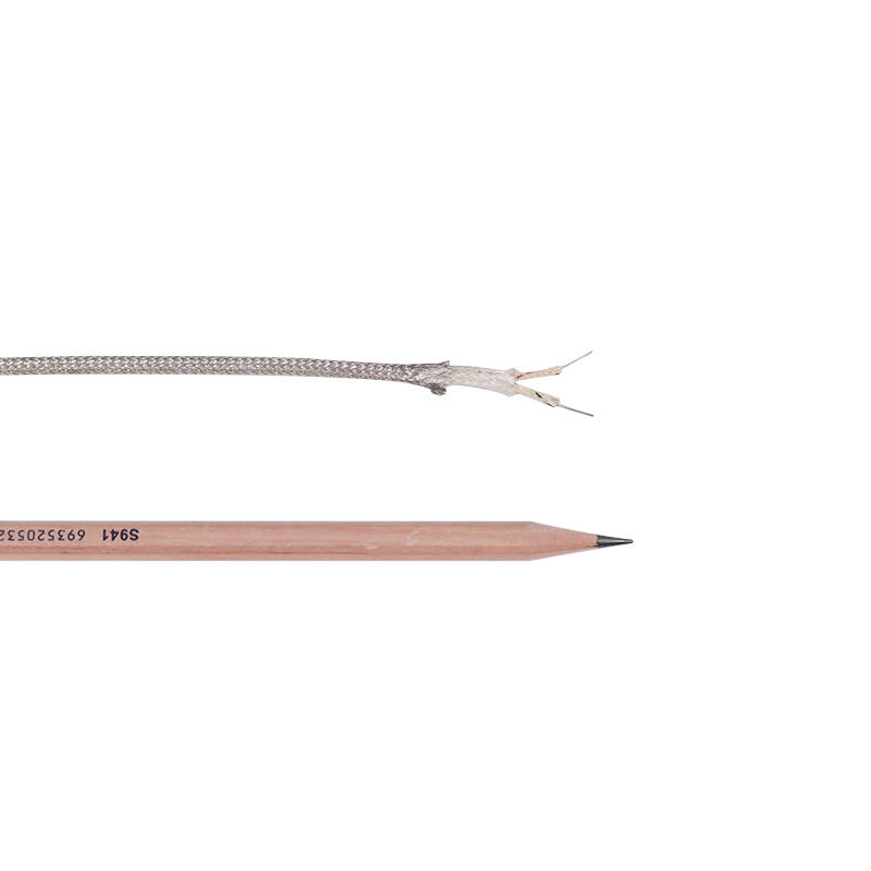 Glass Fiber High-Temperature Stainless Steel Braided Thermocouple Compensation WireFor thermocouple loops, this fiberglass-insulated stainless steel braided compensation wire spans -50 to 1600°C and supports quote or PDF requests.View Product →
Hardware That Handles the Cold Junction for You
Where the cold junction effectively lives depends on where you decide to digitize the signal. Three arrangements cover most industrial installations:
- Direct wiring to a controller or input card, with the reference sensor inside the instrument.
- A head mounted or field transmitter at the sensor, performing compensation locally and sending a 4-20 mA or digital signal to the control room.
- A rail mounted transmitter in the cabinet, for sensors that are awkward to reach.
Moving the transmitter out to the sensor is often the single biggest improvement available. The thermocouple and its extension wiring get shorter, intermediate junctions disappear, and the signal travels most of the distance as a robust current loop instead of a microvolt level EMF. Our integrated temperature transmitters are built for exactly this arrangement, with the reference junction handled inside the housing rather than at the far end of a long cable run.
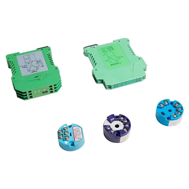 Integrated Temperature Transmitter with SBWR/SBWZ Two-Wire 4-20 mA OutputSBWR/SBWZ modules install in thermocouple or RTD connection boxes, shortening sensor wiring and outputting linear 4-20 mA for measurement and control.View Product →
If you are weighing analog against smart transmitters, our guide on how temperature transmitters work covers accuracy classes, drift and selection criteria in more detail.
Practical Habits for a Reliable Cold Junction
During installation
- Keep every terminal connection of one thermocouple inside a single isothermal zone instead of splitting it across two blocks.
- Do not mount terminal blocks or transmitters directly above contactors, drives or power supplies.
- Use thermocouple grade wire, respect its temperature rating, and check polarity before tightening.
- Shield terminals from direct airflow and sunlight, particularly in outdoor enclosures.
In service
- Verify the loop against a known reference, such as a dry block calibrator or a simulated millivolt input.
- Inspect terminals for oxidation and re-torque them after the first thermal cycles of a new installation.
- Record cabinet temperature alongside process readings; seasonal drift in a stable process usually points to the enclosure, not the sensor.
On the control side, a controller with sound reference junction handling takes this work off the operator's hands. Our compact digital PID temperature controllers accept thermocouple inputs directly and manage the cold junction internally, which keeps small skids, incubators and ovens simple to build and straightforward to maintain.
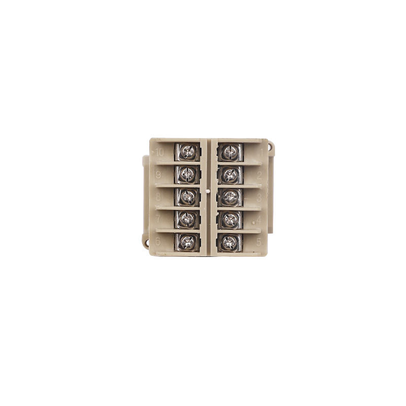 Compact Digital PID Temperature Controller xmtg1001 with Internal Cold Junction HandlingFor small skids, incubators or ovens, this 48×48 mm controller accepts thermocouple inputs and manages the reference junction internally with relay output.View Product →
Treating the Loop as One System
Cold junction behaviour is one part of a measurement loop, and the rest of the loop deserves the same attention. Sensor type, sheath material, protection tube, mounting method and cable route all interact, and a perfectly compensated transmitter cannot rescue a thermocouple installed where it will not survive. In petrochemical plants, a waterproof, wear resistant thermocouple paired with correctly rated compensation wire usually matters more than a small difference in catalog accuracy. In high temperature processes, platinum-rhodium and tungsten-rhenium sensors keep the measuring junction reliable where base metal types would not last. You can see how these combinations come together across our industry application pages.
None of this has to be complicated. Accept that a thermocouple reports a difference rather than an absolute value, give the reference junction a stable and isothermal home, use wire that matches the sensor, and let a well specified transmitter or controller handle the arithmetic. Do those four things and the cold junction stops being a hidden source of error and becomes what it should be: a quiet, understood part of the measurement loop.
Recommended Products

PRODUCT
CONTACT INFO.
-
 +86-181 1593 0076 (Amy)
-
 +86 (0)523-8376 1478
-
 [email protected]
-
 No. 80, Chang'an Road, Dainan Town, Xinghua City, Jiangsu, China
QR CODE